The main failure mode of the hydraulic hose assembly
The main failure mode of the hydraulic hose assembly can be summarized into two categories, one is the quality problem caused by the raw material defect of the hose itself, and the other is the failure caused by the process in the production process of the hose assembly, which is mainly manifested as the oil leakage at the clamp. This paper mainly analyzes and discusses the type of joint structure of the clamping part. If the structural design of the clamping part is unreasonable, it is easy to have quality problems such as oil leakage at the clamping part during use, and even safety accidents caused by the pulling out or breaking of the joint.
1 Hose connector type
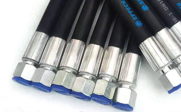
The hose joint related to the clamping part is mainly composed of a joint core, a sleeve and a connecting piece. According to the different reliability connection methods of hose joints and rubber hoses, it can be divided into split joints and integrated joints. The split-type joint core, sleeve and nut are separated, and after assembly, the pressure and hose form an inseparable whole. Before the integrated joint is pressed on the hose assembly, the sleeve, the joint core and the nut are connected as a whole by the buckle withholding structure and the withholding process.
1.1 Split hose connector
The rubber hose used for split joints can be divided into two types of stripping and stripping and stripping.
Stripping and pressing process: After the hose is fed, it is necessary to strip the outer rubber layer at both ends of the hose to a certain length, so that the steel wire reinforcement layer and the sleeve tooth groove can better contact, when the sleeve is permanently plastic deformed by the external force of the clamping machine, the tooth top and the steel wire reinforcement layer are firmly occluded together to prevent the joint from being pulled out by high pressure impact. This process is suitable for wire braided pipe and wire wound pipe without inner lock structure core.
Stripping and pressing process: the hose needs to strip a certain length of inner and outer rubber after unloading, this process method is suitable for the internal lock type joint core with anti-pulling structure. Usually used for ultra-high pressure wire wound pipe.
1.2 Integrated hose connector
The integrated joint is mainly used for non-stripping and pressing process. There is no need to strip the internal and external glue after the hose is fed, and the processing technology is simple after assembly. However, the stability of the size of the hose is relatively high, and it is usually suitable for imported braided pipes with stable size.
2 Structure of the clamping part of the hose joint
Whether it is a split joint or an integrated joint, the key to the clamping part of the hose joint is the tooth shape of the core and the inner tooth structure of the sleeve, which determines the sealing performance and clamping strength of the hose assembly after clamping, and most of the failure modes of the hose assembly are also concentrated in the leakage of oil at the hose clamping, pipe explosion or joint withdrawal.
2.1 Connector core
The outer circular tooth profile and structural size of the joint core, and the structural design of different enterprises are also various. According to the mechanical properties of the inner adhesive, it is usually designed into a sawtooth groove structure, and the Angle between the outer hypotenuse of the core and the axis is generally not more than 20°. Because the joint core and the rubber hose are interference fit, there should be no sharp burrs in the part where the core contacts with the inner rubber, so the top of the tooth and the bottom of the tooth are smoothly transferred through the fillet, and the fillet radius is 0.2mm to 0.5mm. The rounded Angle at the end face of the core can be adapted to be larger to prevent the sharp edges from damaging the rubber layer in the hose when the core is assembled and crimped. This type of joint core is usually used for wire braided hoses.
For the wire wound pipe, more use of the internal lock structure of the joint core. This type of joint core is specially designed with a semi-circular anti-pulling groove to prevent the joint from pulling out from the hose under the action of high pressure impact. This type of hose joint has high reliability and long service life, mainly used in ultra-high pressure large diameter wire wound pipe and wound pipe under harsh conditions.
2.3 Sleeve
The outer surface of the sleeve is a smooth cylinder, and the inner surface is a certain number of trapezoidal tooth slots. In order to ensure that the inner teeth of the sleeve can penetrate the outer rubber layer of the hose and enter the steel wire reinforcement layer, the tooth tip size of the sleeve is designed to be narrow, and the width is 1-2mm. Smooth transition with R0.2mm arc at acute angles. After the joint and the hose are assembled, the inner teeth of the sleeve firmly bite together with the steel wire layer under the action of the pressing force to play a sealing role.
2.4 Process requirements of the sleeve
1) The tip of the sleeve should be made into a circular arc to avoid sharp tip and operate the steel wire reinforcement layer;
2) The diameter of the top of the first tooth near the hose end should be larger than the diameter of the top of the other teeth to avoid stress concentration caused by internal glue accumulation after compression;
3) The coaxiality between the inner circle outline and the outer circle of the sleeve is controlled within 0.1mm;
3. Determine the clamping parameters
The buckle parameter is the key factor in the hose assembly, which directly affects the reliability and safety of the hose assembly. Insufficient pressure can lead to hose joint withdrawal or oil leakage, too much pressure, it will make the inner rubber too compressed resulting in hardening of the inner rubber, loss of elasticity and oil leakage.
In actual work, according to different types of hose structure parameters and sleeve, core structure type to be modified, the commonly used method in the industry is to calculate the reference value according to the theory and then through the performance test (including pressure test, burst test, pulse test) to verify. Further revision and determination of final buckle parameter values.
4 Failure mode analysis
4.1 Type of failure: The main failure modes caused by the structure of the hose joint and the clamping process are: oil seepage at the clamping place, hose joint withdrawal, bulging at the clamping root and tube explosion.
4.2 Fault Causes:
1) Oil leakage at the pressure is a common failure mode of hydraulic hose assembly, which is mainly caused by the large deviation of the inner diameter of the hose and the outer diameter of the steel wire layer, the uneven thickness of the inner rubber layer, the aging elasticity of the inner rubber, the unqualified size of the pipe connector, the mismatch between the hose and the pipe joint, and many other factors;
2) Pulling out of the pipe joint under high pressure is a very dangerous quality accident, which will cause personnel injury and property damage in serious cases. The main reasons for joint pulling out are: unreasonable design of clamping parameters, unreasonable design of tooth shape structure of joint and sleeve, too small clamping amount, and the steel wire reinforcement layer can not be tightly fastened with the teeth end of core and sleeve.
3) The buckle root bulge and burst pipe, the possible reasons are that the system pressure is higher than the pressure bearing capacity of the hose, the hose assembly is twisted and installed, or the buckle root is in a state of repeated frequent bending for a long time.
5 Solutions
For the hose with large size wave, the method of purchasing group clamping is to adopt different clamping parameters according to the diameter difference of the outer and inner diameter of different steel wire layers, so as to reduce the influence of size deviation on the clamping effect. Secondly, the joints of different types of structures need to choose a reasonable amount of clamping, which should not be too large or too small. The buckle products should be fully verified by various performance tests, such as pressure resistance, blasting, pulse and other tests, under the support of relevant industry standards.
6 Closing remarks
This paper discusses the structure types of the core and sleeve of the hose joint and the main failure modes of the hydraulic hose assembly, analyzes the causes and how to choose the appropriate clamping amount to avoid the low performance of the hose assembly. It provides strong support for the reliability improvement and control of hydraulic hose assembly.
Categories
News
Contact Us
Contact: China Zhuofan Hydraulic Co., Ltd
Phone: +8613184968882
Tel: +8613184968882
E-mail: zfhydraulic@163.com
Add: Jing County, Hengshui City, Hebei Province, China